Thermovision in practice
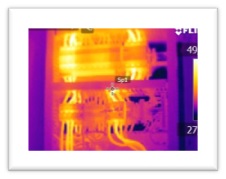
The use of thermal imaging cameras is relatively rare in Slovakia. There is a lot of talk about them, but few companies and people use their potential. Available thermal imaging cameras (thermovision) find use in a large number of fields, from construction, through industry, to installations. We use thermal imaging cameras in wiring, switchgear, construction and during inspections and revisions of electrical equipment, where they can identify faults that are not visible to the naked eye and would otherwise be undetectable. Thermal imaging thus simply prevents a major fault.
Thermal imaging of installations
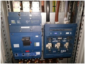
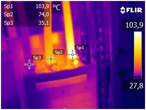
Example from practice: in the pictures is the electrical switchboard for a small dye house that was inspected this year and the wiring was serviced a month ago. Immediately after removing the switchboard cover it was clear that something was wrong! On the grey cable of the main supply there is a slight scorching of the wiring, when scanned this supply reached a temperature of 103 oC. If this problem had not been addressed, a fire could have started and production would have been shut down, resulting in a large loss for the company.
When using thermal imaging cameras, it is always necessary to follow the procedures for the correct use of the cameras, the technical description and to take into account the characteristics of the equipment in question.
The heat generated by a fault in the transition joints and in the line does not always result in a fire or a major fault in the line, but also in financial losses in the form of heat loss and line loss. To illustrate, in industry, with a transition resistance of 0.02Ω and a current of 250A, the annual losses 10 950kW/h, at an electricity price of 0,129 Eur/kWh is annual loss "not insignificant" 1412,55 Eur. In households, a resistance of 0.1Ω at a current of 20A causes a loss of 350kWh per year, which amounts to 45.15 Euros per year. We repair such deficiencies promptly and with the help of a developed procedure we can adjust the transient resistance to the minimum value.
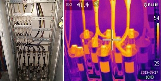
Table of losses at individual resistances:
U1 | U2 | dU | R | I | P | Energy losses for | ||
|
|
|
|
|
| The Hour | Day | year |
(V) | (V) | (V) | (Ω) | (A) | (W) | (kW. h) | (kW. h) | (kW. h) |
230 | 229,9 | 0,1 | 0,005 | 20 | 2 | 0,002 | 0,048 | 18 |
230 | 229,8 | 0,2 | 0,01 | 20 | 4 | 0,004 | 0,096 | 35 |
230 | 229,5 | 0,5 | 0,025 | 20 | 10 | 0,01 | 0,24 | 88 |
230 | 229 | 1 | 0,05 | 20 | 20 | 0,02 | 0,48 | 175 |
230 | 228 | 2 | 0,1 | 20 | 40 | 0,04 | 0,96 | 350 |
230 | 225 | 5 | 0,25 | 20 | 100 | 0,1 | 2,4 | 876 |
Table published in Světlo magazine 2014/2
Industry and distribution
Thermal imaging is of great benefit in industrial, high voltage and renewable energy applications.
When inspecting transformers, high voltages and wherever it is not possible to get close to the equipment for safety reasons, thermal imaging plays a key role. With the help of imaging, it is possible to detect overloading and overheating of important components, such as with the 22 kV transformer in the picture.
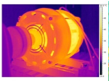
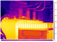
In industry, it is possible to observe rotating and non-rotating machines and the effect of friction on individual components. According to this, it is possible to decide how to proceed or how to carry out remedial work. With photovoltaic panels, it is possible to measure whether they are working properly and whether HOT-SPOTs are being formed on them, which have an adverse effect on the entire production.
Thermal imaging of buildings and interiors
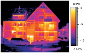
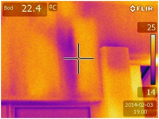
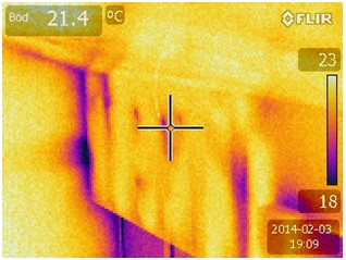
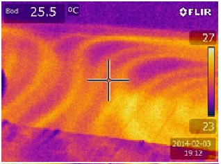
Thermal imaging is a very popular tool in the construction industry where it is possible to monitor heat leaks from a building. It can also be used to find hidden heating in the floor or walls, or to locate leaks. Few people realise that this is the way to check the insulation and the correct execution of the work. Or, in the case of a renovation, to locate the heating system and find where it can be avoided. Thermal imaging measurements can also be used from the inside. The following pictures show poor insulation workmanship in a duplex apartment.
